-
Structure and Special Feature
-
Load Rating and Service Life Linear Motion System
-
Factors that affect travel life
-
Load Considertion
-
Mean Effective Load at Varying Load
-
SAMICK Support Rail Unit
-
SAMICK LM Shaft
-
SAMICK Shaft Support
-
Self-Aligning Linear Bushing
-
SAMICK LINEAR BUSHING
-
Guide Master
-
Referance Data
> SAMICK LINEAR BUSHING > Load rating and Travel Life
The Load rating of SAMICK Linear Bushing can be affected by the balls orientation against the Load. The Basic Load rating in the table is the Load rating of Linear Bushing when 1 (one) Ball circuit are just beneath the load. As shown in Table, If the Ball are located on symmetrical position against the Load, the Load rating will be increased and the travel life will be extended
Load ratings and Orientation of Balls
| Orientation of Balls | |||
|---|---|---|---|
| No. of Ball Row | 4 Row | 5 Row | 6 Row |
| Max. Load |  |
 |
 |
| Equation | F = 1.41 × C | F = 1.46 × C | F = 1.26 × C |
| Max. Load |  |
 |
 |
| Equation | F = C | F = C | F = C |
Basic Dynamic load rating(C) and travel life
The travel life of a Linear Bushing is determined largely by the quality of the shaft. The Basic Dynamic load rating is maximum continuous load that can be applied to the Linear Bushing with 90% of reliability achieving after 50km traveling under normal conditions. The nominal travel life can be calculated by follow equation.

Practically, other factors (Hardness factor, Load factor, Contact factor, etc) will affect the life as followsPractically, other factors (Hardness factor, Load factor, Contact factor, etc) will affect the life as follows

Equivalent factor and Travel life
If a Linear Bushing or two Linear Bushings laid beside one another on one shaft, and the moment load is applied, calculate the Equivalent load.

If the moment load and the radial load are applied, the travel life can be calculated by the sum of the moment load and the radial load. From the above equations, the stroke and frequency are constant; the travel life can be calculated by following equation

Equivalent factor for Linear Bushing
| Equivalent factor (K) | |||||||
|---|---|---|---|---|---|---|---|
| P/N | 1EA | 2EA | P/N | 1EA | P/N | 1EA | 2EA |
| LM 5 | 1.253 | 0.178 | LM 5L | 0.223 | LME 5 | 0.669 | 0.123 |
| LM 6 | 0.553 | 0.162 | LM 6L | 0.201 | LME 8 | 0.514 | 0.116 |
| LM 8S | 0.708 | 0.166 | LM 8L | 0.151 | LME 12 | 0.389 | 0.090 |
| LM 8 | 0.442 | 0.128 | LM 10L | 0.118 | LME 16 | 0.343 | 0.081 |
| LM 10 | 0.389 | 0.101 | LM 12L | 0.113 | LME 20 | 0.291 | 0.063 |
| LM 12 | 0.389 | 0.097 | LM 13L | 0.107 | LME 25 | 0.209 | 0.052 |
| LM 13 | 0.343 | 0.093 | LM 16L | 0.096 | LME 30 | 0.167 | 0.045 |
| LM 16 | 0.279 | 0.084 | LM 20L | 0.082 | LME 40 | 0.127 | 0.039 |
| LM 20 | 0.257 | 0.071 | LM 25L | 0.060 | LME 50 | 0.105 | 0.031 |
| LM 25 | 0.163 | 0.054 | LM 30L | 0.053 | LME 60 | 0.093 | 0.024 |
| LM 30 | 0.153 | 0.049 | LM 35L | 0.050 | |||
| LM 35 | 0.143 | 0.045 | LM 40L | 0.043 | |||
| LM 40 | 0.117 | 0.040 | LM 50L | 0.034 | |||
| LM 50 | 0.096 | 0.032 | LM 60L | 0.031 | |||
| LM 60 | 0.093 | 0.028 | |||||
Note 1) The equivalent factor for LMF/K/H, LMFP/KP/HP and SC types are same as LM type.
Note 2) The equivalent factor for LMF-L, LMK-L, LMH-L and SCW types are same as LM-L type.
Note 1) The equivalent factor for LMEF/K/H and SCE types are same as LME type.
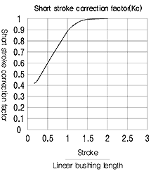
Short stroke Applications
In applications when the stroke is short, the life of the shaft is shorter than that of the Linear Bushing. In short stroke applications, the required dynamic load rating must be multiplied by the shot stroke correction factor (Kc) found on Fig right side.


