-
Structure and Special Feature
-
Load Rating and Service Life Linear Motion System
-
Factors that affect travel life
-
Load Considertion
-
Mean Effective Load at Varying Load
-
SAMICK Support Rail Unit
-
SAMICK LM Shaft
-
SAMICK Shaft Support
-
Self-Aligning Linear Bushing
-
SAMICK LINEAR BUSHING
-
Guide Master
-
Referance Data
> SAMICK LINEAR BUSHING > Installation Guide
Recommended Tolerance of Housing bore for SAMICK Linear Bushing are in Table. Normal fit is standard, but for without clearance, pressed fit is also available.
| Type | Case | ||
|---|---|---|---|
| Part number | Grade | Normal fit | Pressed fir |
| LM | Higher(H) | H7 | J7 |
| LME | - | H7 | K6,J6 |
| LMF/FP LMK/KP LMH/HP LM_L LMF/FP_L LKM/KP_L LMH/HP_L LMFM |
- | H7 | J7 |
Clearance of Outer sleeve and Shaft
Normal fit is standard for using of Linear Bushing with LM shaft. And, for without clearance, tight fit is available. Next table shows outer diameter tolerance of shaft.
| Type | LM Shaft | ||
|---|---|---|---|
| Part number | Grade | Normal fit | Tight fit |
| LM | Higher(H) | f6,g6 | h6 |
| LME | - | h7 | K6 |
| LMF/FP LMK/KP LMH/HP LM_L LMF/FP_L LKM/KP_L LMH/HP_L LMFM |
- | f6,g6 | h6 |
Negative diametric clearance should not exceed what is specified in the dimension table.
| Radical Clearance(㎛) | |||||||||||||||
|---|---|---|---|---|---|---|---|---|---|---|---|---|---|---|---|
| Type/Dr. | 5 | 6 | 8S | 8 | 10 | 12 | 13 | 16 | 20 | 25 | 30 | 35 | 40 | 50 | 60 |
| LM(㎛) | -3 | -5 | -5 | -5 | -5 | -5 | -7 | -7 | -9 | -9 | -9 | -13 | -13 | -13 | -16 |
| LME(㎛) | -5 | -5 | -7 | -7 | -9 | -9 | -9 | -13 | -13 | -16 | |||||
Mounting
High holding strength toward LM shaft direction is not required, but just press fit only for mounting is not recommended.
Standard type
Feasible mounting methods are illustrated in Fig 8 and Fig 9. At this moment, fix the linear bushing with retaining rings and cover plates

Retaining ring for Mounting
Retaining ring for LM type SAMICK Linear Bushing are used for mounting as shown in the table below.
| Part number | Retaining ring(mm) | |||
|---|---|---|---|---|
| External (for Shaft) | Internal(for Bore) | |||
| C type | Needle type | C type | Needle type | |
| LM 5 | 10 | 10 | 10 | 10 |
| LM 6 | 12 | 12 | 12 | 12 |
| LM 8 | - | 15 | 15 | 15 |
| LM 8S | - | 15 | 15 | 15 |
| LM 10 | 19 | 19 | 19 | 19 |
| LM 12 | 21 | 21 | 21 | 21 |
| LM 13 | 23 | 22 | 23 | - |
| LM 16 | 28 | - | 28 | 28 |
| LM 20 | 32 | - | 32 | 32 |
| LM 25 | 40 | 40 | 40 | 40 |
| LM 30 | 45 | 45 | 45 | 45 |
| LM 35 | 52 | 52 | 52 | 52 |
| LM 40 | - | 60 | 60 | 60 |
| LM 50 | - | 80 | 80 | 80 |
| LM 60 | - | 90 | 90 | 90 |
Note) The information in the table are common for LM and LM-L type
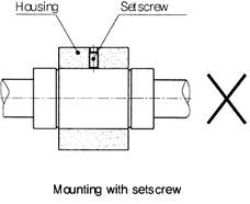
Setscrew mounting prohibited
Mounting a Linear Bushing with a set screw as show in Figure will cause deformation of the outer sleeve and should be avoided.
Flanged type
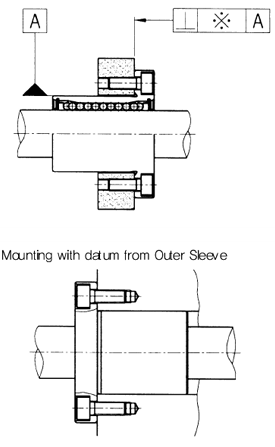
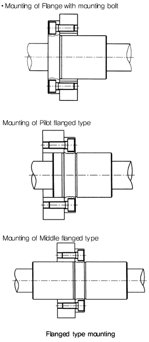
Mounting for LMF, LMK, LMH (included long type), only mounting the flange with mounting bolt can be all of mounting because of its single body shape. Geometric Dimensional Tolerance should be considered when the Outer Sleeve is the datum for installation.
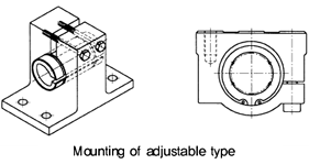
Mounting of Adjustable type
Adjustment of clearance for Adjustable type (AJ) and LM shaft can be obtained by assembling with the adjustable type Housing. In this case, the slotted side of Linear Bushing should be located at 90˚of open side of Housing for equivalent deformation against radial direction.
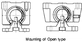
Mounting of Open type
Open type(...OP) also can be used with clearance adjustable housing as shown on Figure. Light pre-load is applied for normal using, but heavy pre-load should be avoided.
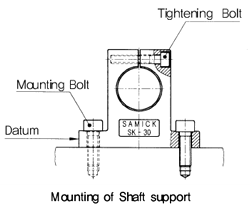
Mounting of Shaft support
Shaft support, SK can be mounted with mounting bolt for table, and LM shaft can be mounted with tightening bolt
Mounting of LM Case Unit
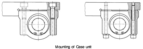
Mounting of SC type Both side mounting of SC(E), SC(E)_W, SC(E)_V type from the top and the bottom side with mounting bolt are both available, and it gives you minimum mounting time.
